Page title
The Sutorbilt blower operates by trapping air with two "figure eight" impellers rotating in opposite directions. This entrapment occurs four times per revolution and efficiently creates pressure and volume for your aeration system.
The Sutorbilt Legend Series features machined cast iron construction of the housing and impellers. Impellers are dynamically balanced to operate without vibration and are permanently fastened to steel shafts. Shaft rotation can be in either direction. To change the inlet/discharge orientation of the blower simply reverse the rotation of the drive motor.
Anti-friction bearings are used throughout. Timing gears and gear end bearings are splash oil lubricated from an oil-tight housing enclosing the timing gears. Drive end bearings are grease lubricated through fittings. High temperature Viton lip type seals prevent the oil and grease from entering the impeller chamber to prevent contamination in your system.
| Sutorbilt Legend Pressure Performance Data |
| Size |
Dia. Inlet & Outlet |
RPM |
7 PSIG |
9 PSIG |
10 PSIG |
12 PSIG |
13 PSIG |
14 PSIG |
| CFM |
BHP |
CFM |
BHP |
CFM |
BHP |
CFM |
BHP |
CFM |
BHP |
CFM |
BHP |
| 3MPQ 3MVPQ |
2" - S |
1,760 |
64 |
3.6 |
59 |
4.6 |
|
|
|
|
|
|
|
|
| 2,265 |
95 |
4.6 |
89 |
5.8 |
87 |
6.4 |
|
|
|
|
|
|
| 2,770 |
125 |
5.5 |
119 |
7.1 |
117 |
7.9 |
112 |
9.5 |
|
|
|
|
| 3,600 |
175 |
7.2 |
169 |
9.2 |
167 |
10.2 |
162 |
12.3 |
|
|
|
|
S = Threaded connections standard NPT. F = Flange connections.
Performance based on standard conditions: Sea Level, 14.7
PSIA, 68°F, 36% Relative Humidity.
For performance with gases other than air or at non-standard conditions,
contact Tri-State Wastewater Equipment's customer service by email at:
info@tri-statewastewater.com, by phone at: 513-342-1668, or by fax at:
513-334-0222, and we would be happy to help with any questions or sizing
information. |
|
|
|
|
|
|
|
|
|
|
|
|
|
|
|
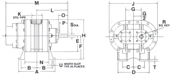
HORIZONTAL CONFIGURATION

| Size | Wt. | Conn. | A | B | C | D | E | F | G | H | J | K | L | M | N | O | P | R | S | T | U |
|---|
| 3MP | 110 | 2 - S | 7-5/8 | 3-1/8 | 2-7/8 | 7-3/4 | 3-7/8 | 5 | 3-1/2 | 8-7/8 | 11-1/4 | 2 | 6-1/4 | 12-3/4 | 4-3/8 | 2 | 1-11/16 | 3/16 | 0.750 | 1/4 | 1/2x3/4 |
S = Threaded connections standard NPT. F = Flange connections. Inlet and outlet connections are the same type and size.
Dimensions are in inches. Weights are in pounds and include factory shipping cartons or pallets. (Actual shipping weight may vary)
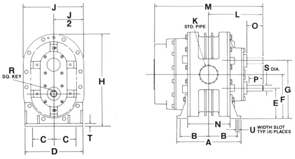
VERTICAL CONFIGURATION

| Size | Wt. | Conn. | A | B | C | D | E | F | G | H | J | K | L | M | N | O | P | R | S | T | U |
|---|
| 3MVP | 110 | 2 - S | 7-5/8 | 3-1/16 | 2-1/2 | 6-3/4 | 4-1/2 | 6-1/4 | 8 | 11-7/8 | 7-3/4 | 2 | 6-1/4 | 12-3/4 | 4-3/8 | 2 | 1-11/16 | 3/16 | 0.750 | 1/4 | 1/2x3/4 |
S = Threaded connections standard NPT. F = Flange connections. Inlet and outlet connections are the same type and size.
Dimensions are in inches. Weights are in pounds and include factory shipping cartons or pallets. (Actual shipping weight may vary)
The Flex-Mount design makes it easy to change from a right hand drive to a left hand drive on the horizontal unit by unbolting the feet and rotating the blower 180°. To change a bottom hand drive to a tip hand drive on a vertical unit, simply rotate the blower 180°. To quickly convert a horizontal blower to a vertical (90° rotation), simply bolt on a set of vertical mounting feet (sold separately).
The plane of the shafts determine whether a blower is vertical or horizontal, not the inlet and outlet ports. Be sure to torque bolts down and reverse the oil drain and fill plugs. Inlet/discharge pipe connections are the same size, female NPT.
